|
Aopen KF45 Case w/ 250W PSU

Click to enlarge...
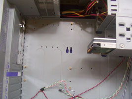
In the above photo you can see the standoffs installed into the motherboard
tray (as suitable for the motherboard going to be installed, an ASUS CUPLE-VM.
All of the holes are labeled with a letter or a combination of a few letters.
These letters correspond to a key which is also written on the motherboard tray.
This key is there for the purpose of simplifying the installation of motherboards
as it shows you which screws correspond to which form factors, however you may
find this does not definitively suit your motherboard - the CUPLE VM required
the bottom right stand-off to be down a hole from the recommended form factor
guide, so be warned - while it makes it easier it is still best to double check,
had I not I may just have fried the motherboard and components due to a short.

Click to enlarge...
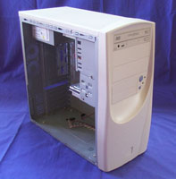
Here is the case with the PSU, CDROM and HDD installed ready for the motherboard
and NIC. Note the buttons and indicators for power/HDD usage on the front and
the location of the case badge mounting point. The buttons are easy to press
and the LED's do their job, displaying power and HDD access fine (as a LED typically
does :D). The case badge location may end up being
cut off if you choose to perform the modifications I suggest in the space of
the next few pages.
Next we look at the system in the case and a brief overview of it as a case
for the audience it is targeted at.
<< Previous Page || Next Page >>
| 
